Ro 80 padmagrün from 1969 - restoration
Good Morning everyone
First of all I'm sorry to write in English but I don't speak German.
I bought a Ro 80 padmagrün from 1969 about a month ago and I'm working on its restoration.
In particular I would like to understand how the ignition system of this car works to restore it to its original condition or to improve it if necessary.
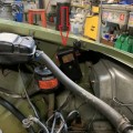
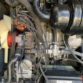
Meanwhile, I describe how it is now.
The car's first owner installed an electronic module to drive the spark plugs avoiding the high current in the pins. This is not an electronic control unit (HKZ) but a simpler device. Furthermore, only one pair of pins is used and the 2 spark plugs of the same rotor are turned on simultaneously.
The second owner then made adapters to use standard spark plugs instead of his specific plugs.
Is there anyone who can provide a clear ignition scheme for my car in order to restore it as it was originally?
My distributor does not have the external capacitors I saw in the repair manual. Is this correct or am I missing something?
To avoid the high current on the points, do you have to pass through two HKZ control units or can you use cheaper pickups?
I would like to build a new set of the ignition cables (between distributor and spark plugs and between distributor and coils).
What kind of cable is suitable (diameter, impedance, etc.)?
Are there available connectors for the spark plugs and distributor like the originals (90°)?
Thanks in advance for your help.
Best Regards
Bruno Zorzolo
- Anmelden oder Registrieren um Kommentare zu schreiben

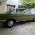
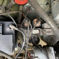
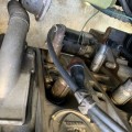
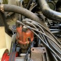
 Gruppenbilder ansehen
Dear Bruno, congratulations with your nice Padmagrün Ro, hope that you can make a successful restoration and then enjoy the ro80 to the full!!
To your questions:
The electrical diagram is as simple as you can imagine: 12V supply to the ignition coil, primary coil. The other end of the primary coil is connected to the distributer contact, and this contact grounds the coil. There should also be a capacitor over the contacts. The special aspect of the Ro is that the engine is equipped with 2 circuits, each with its own ignition coil, contact and capacitor.
You can restore the ignition to the original situation. Then you must add the capacitors, they may have been removed when the electronic ignition module was installed. The capacitors are necessary to create enough primary voltage (in cooperation with the coil) and they avoid excessive arcing and wear of the distributer contacts,
However, Ro specialists do not recommend to restore this original situation as it just exactly contains one of the design flaws with which the Ro entered the market. Although it is a double ignition system, the spark is not very strong and the ignition timing needs frequent readjustment because of the wear of the contact tips.
The ideal situation is a reconstruction of the ignition with 2 HKZ. Then you will need two new ignition coils, the type that is designed for use with the HKZ, you cannot use ordinary ignition coils. You can keep the 2 distributer contacts, the wear of the contacts will be minimized because of the very low current. Of course you can also try other, more modern solutions with electronic ignition devices.
You can use standard ignition cable with copper core and use the original spark plug caps with built-in 5 kOhm resistor and the connectors to the distributor cap with resistor of 1 kOhm. They have been produced in masses by Bosch and you will be able to find these.
Wishing you lots of success, Pieter
Dear Pieter
Dear Bruno, congratulations with your nice Padmagrün Ro, hope that you can make a successful restoration and then enjoy the ro80 to the full!!
Thank you very much. I hope so!
To your questions:
The electrical diagram is as simple as you can imagine: [...]. The special aspect of the Ro is that the engine is equipped with 2 circuits, each with its own ignition coil, contact and capacitor.
Ok. If I understand correctly, there are 2 separate and slightly staggered ignition circuits. Considering the rotors rotation, the second spark plug of each stator is turned on slightly earlier than the first.
You can restore the ignition to the original situation. [...]
Ok
However, Ro specialists do not recommend to restore this original situation [...]
I understand.
The ideal situation is a reconstruction of the ignition with 2 HKZ. [...]
I don't argue that this is the best solution but it is also very expensive: each HKZ costs € 329!
I rather thought of replacing the group of capacitors with 2 pickups, that is two power circuits to preserve the pins from excessive currents.
You can use standard ignition cable with copper core [...]
About the spark plug connector I find this: https://www.auto-doc.it/bosch/1155170
given for NSU Ro 80, but the resistance is 1kOhm instead of 5kOhm (!?) As for the connector to the distributor there would be this but it is out of stock. https://www.auto-doc.it/bosch/1155158
Furthermore all these connectors are very expensive (more than € 20 each). It takes about € 250 to build the entire wiring!
The last datum I need is the heat rating of the spark plugs. If I am not wrong the 2 spark plus of the same stator have different heat rating, right?
Wishing you lots of success, Pieter
Thanks again, Bruno
Dear Bruno, indeed, a reconstruction with 2 HKZ is very expensive, therefore you can also look to alternative ignition devices. I think it is no problem to leave the 2 distributer contacts in place and let them trigger 2 devices of your choice. Then you can also leave the conventional ignition coils in place.
You can also look for NGK spark plug caps, I found some with 5 Kohm at a price of 4 - 5 €. These are also suitable for your Ro.
I know that in the past, the 4 plug motor used 2 plugs of the type Bosch MAG 310 and 2 of the type Bosch Mag 340. But these are very hard to find. I have to ask on this spot if other club members have a suggestion for replacement plugs for the 4-plug engine that are available now! (I drive a 2-plug engine...)
Best regards, Pieter
Hello Bruno,
Your parts dealer also offers a 5k spark plug plug: https://www.auto-doc.it/beru/991776
And the plug for the distributor side: https://www.auto-doc.it/search?keyword=VESO112
Cable in copper / silicone: https://www.auto-doc.it/search?keyword=0300800023
Crimp sleves for the cable ends (to connect to the plugs): https://www.auto-doc.it/search?keyword=0901300002
These Beru parts seem to be approx. half the cost of the Bosch parts.
You normally need a special crimping tool for the cable sleves (https://www.auto-doc.it/search?keyword=ZAZ3). I am not sure if mounting of the sleves is also possible with standard tool / pair of pliers, but it probably is with a little extra work.
Bests
Holger
Hello Bruno,
A schedule for a 2 spark plug engine can in my opinion not be a problem. I don't have it digital but there will be members who do.
The ignition of a 2 spark plug engine like yours is very simple. It's the conventional ignition as Pieter said. The only thing that strikes you is that it is a 6V installation that works on 12V. This peculiarity was probably necessary to spark and burn the quickly polluting spark plugs clean. That is also the reason you have to replace the breaker points very quickly becaus of the higher current.
The external capacitors are only needed when you build everything back to breaker points. With the module you have in it, just a transistor ignition module, you don't have to.
But why without electronic ignition? This is realy a good improvement I realy can recommend. You need only two of them, not one. Just make two circuits. To find such a second unit as you have already can be a problem. Instead, you can use Velleman's building kits, for example.
https://www.velleman.eu/products/view/?id=8946
Because some old components are used here, e.g. TIP162, I've developed one myself that's better and has less components. Connection 2 goes to the breaker points.
It was not for my Ro80 but for my Opel from the seventies.
For ignition cables I recommend you the same as Pieter does. But I go one step further. If you measure your distributor divider on resistance and it has 0 ohm then I advise you to put interference caps of 5k ohm or so on the spark plugs. If the distributor divider itself has a resistance, you can even omit the interference caps on the spark plugs. Every resistance gives a loss and unnecessary losses should be avoided. I know that with the 1 spark plug engine the distributor divider itself has a resistance and therefore you can leave out the interference caps on the spark plugs.
MfG
Alexander
Ciao rekord
Thanks for your suggestions!
I will search, or build, 2 devices like your to drive the coils.
For ignition cables I recommend you the same as Pieter does. But I go one step further. If you measure your distributor divider on resistance and it has 0 ohm then I advise you to put interference caps of 5k ohm or so on the spark plugs. If the distributor divider itself has a resistance, you can even omit the interference caps on the spark plugs. Every resistance gives a loss and unnecessary losses should be avoided. I know that with the 1 spark plug engine the distributor divider itself has a resistance and therefore you can leave out the interference caps on the spark plugs.
Ok. I measure resistance and adjust accordingly.
Ciao, Bruno
Hello rekord
I decided to adopt electronic ignition modules and purchased 2 ELECTRONIC TRANSISTOR IGNITION Velleman.
The technical data sheet of this device says that the maximum current is 4A. Now, if the output voltage from the coils is 25.000V, the resistance between distributor and spark plugs must be at least 6 kOhm, in order not to exceed the maximum allowed current: 1 kOhm at the connector of the distubutor + 5 kOhm at the spark plug connector, like suggests Pieter.
Do you agree?
Ciao, Bruno
Hello Bruno,
Although the question is addressed to Alexander I feel so free to give an answer. You may have calculated that 4*6000 = 24000, and that is about 25 kV. But it has nothing to do with it. Because these 25.000V are generated in the secondary coil of the transformer. But the electronic device has to switch the current through the primary coil. Here the voltage will only rise to 300-400V. The device you selected is designed for this job so I think it will just be OK.
Best regards, Pieter
Hello Pieter
You're right, I got confused. The transistor drives the primary coil and not the secondary one.
Hi Bruno, Pieter,
I was just preparing an answer but Pieter was quicker! Well done.
Anyhow, I assume they are older ignition coils you have. Then the current through them is usually around 3A. More modern ignition coils with a much higher ignition voltage have a much higher primary current. Think of 7 to 10 A. The Velleman is not suitable for that. Keep that in mind.
Can you post a picture of your ignition coils and are you sure that these ignition coils are suitable for 12 V and not 6 V as it was originally?
The resistors in the distributor divider and spark plug suppress the harmonics that are created by sparks and that interfere. The less resistance, the more harmonics, the more interference but also more ignition power. To include an ohmic resistor in the line brings nothing but loss of ignition power.
MfG
Alexander
Can you post a picture of your ignition coils and are you sure that these ignition coils are suitable for 12 V and not 6 V as it was originally?
Hi rekord, here are my coils...
https://www.dropbox.com/s/1ok9ytpc97et5nw/bobine1.jpg?dl=0
https://www.dropbox.com/s/wlovkb1u0egk6m4/bobine2.jpg?dl=0
https://www.dropbox.com/s/566d69l29sknk2o/bobine3.jpg?dl=0
Hello Bruno,
That still looks like the original 6 Volts to me. Velleman then tells you what you need to do to convert the basic 12V circuit to 6V. Just to be sure I would start with 12V. If that doesn't work, then convert to 6V.
By the way, keep in mind that ballast resistor, that big thing next to one of the ignition coils. This resistor is bridged when starting the engine and is used between the ignition coils when the engine is running. If the Vellemankit converted to 6V is set to 12V, so when starting, it will break down.
MfG
Alexander